eCTF Breakout Board
Warning
ARCHIVED PAST COMPETITION, FOR REFERENCE ONLY
The 2024 eCTF creates an interconnected system. In order to ensure signal integrity and ease in setup, the organizers have created the eCTF 2024 Breakout Board.
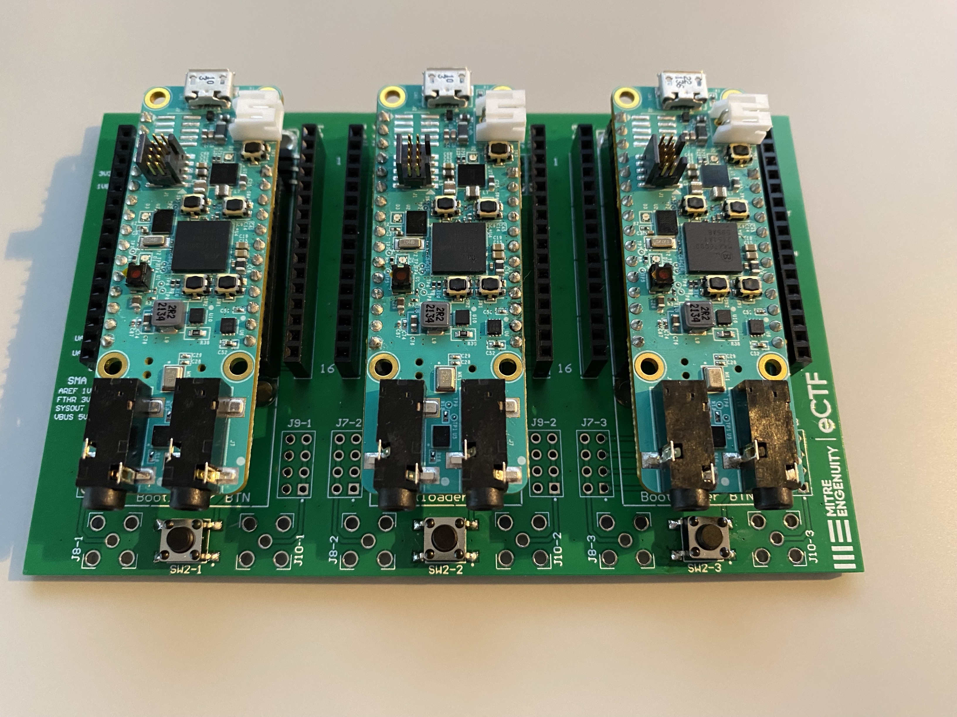
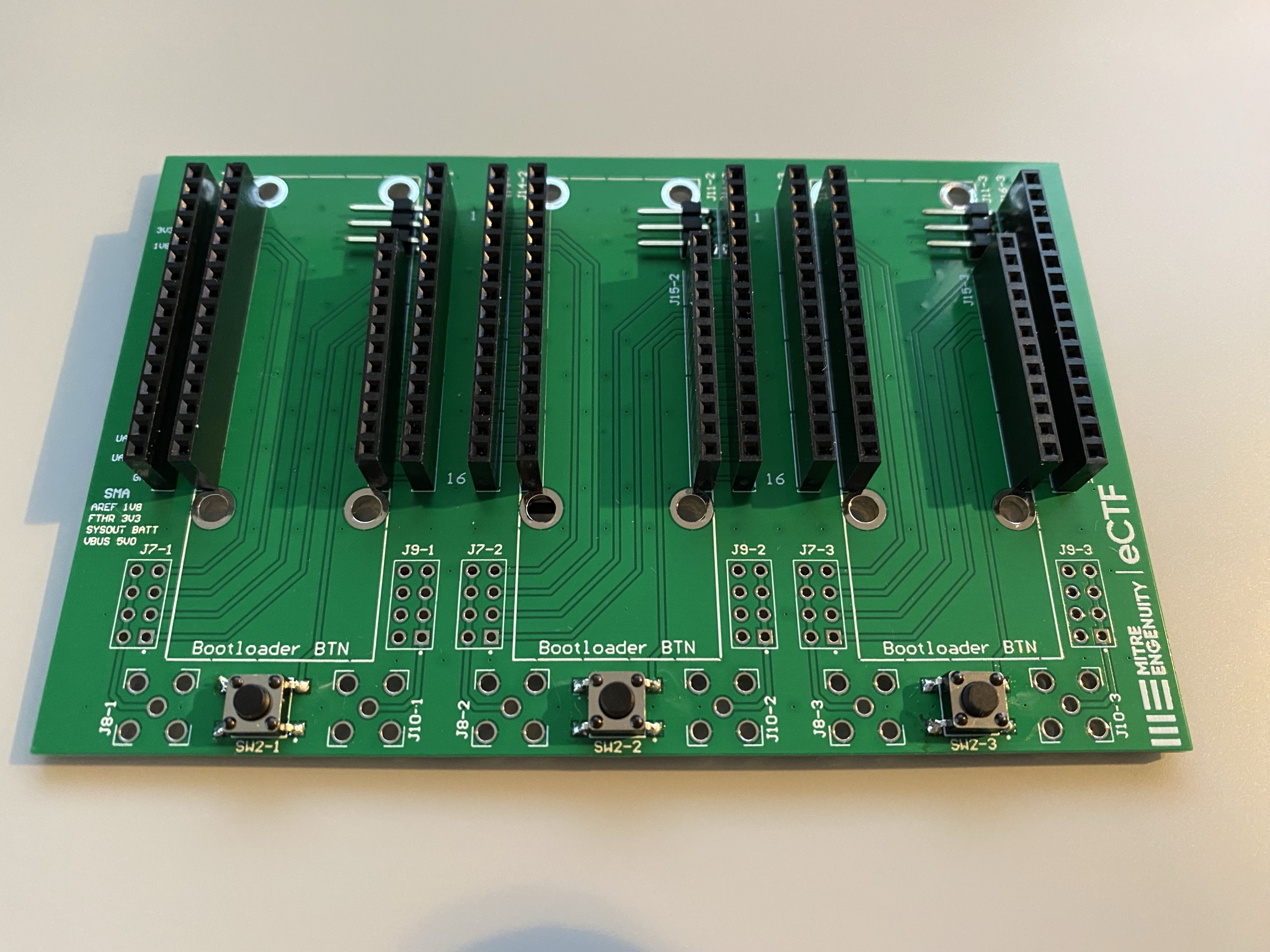
The eCTF Breakout Board consists of 3 “feather” style sockets for the MAX78000FTHR development boards. The board handles connecting the i2c bus of the MAX78000FTHR boards. The breakout board additionally includes headers for easy access to the pins of MAX78000FTHR. These pins are labeled on the far left and the far right of the breakout board.
The breakout board includes a Bootloader Button that can be utilized for switching into bootloader mode with the eCTF Bootloader.
The board includes hard points for terminating soldered wires to the breakout board. These connectors are labeled as USER1, USER2, and USER3. The board additionally includes a selectable jumper identified as J7 and footprints for SMA connectors. These connections are for advanced use, and can be populated by teams as required. The SMA connector and selectable jumper is able to switch between 5V, SYSOUT, 3.3V, and 1.8V signals.
To assemble the full system, simply populate the MAX78000FTHR boards into the breakout board. Connection of the boards through the included USB hub is recommended to simplify cycling power supply to the boards. Once assembled the system should look as shown below.