Removing the Secure Bootloader
Warning
ARCHIVED PAST COMPETITION, FOR REFERENCE ONLY
Attack phase boards come with a secure bootloader preinstalled, which disables debug functionality. However, some teams may wish to clear this bootloader and reuse these boards as normal development boards for future years. This section describes the process to unlock the MAX78000FTHR attack boards.
Warning
This process is irreversible. Once you clear the attack bootloader, you will not be able to re-install it.
Before starting the process, you will need to download the unlock.py script and the secrets file
that matches the year of the board you wish to clear.
STEP 1: First, you must place the device into bootloader mode. To start, power off or unplug the board and ground the UART0 RX pin and SWDCLK pin. These pins are not available on the pin headers but are instead accessible on the pads as highlighted in Figure 1.
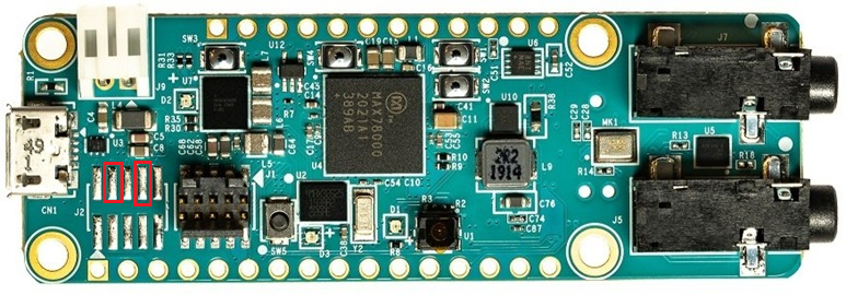
Figure 1. Analog Devices MAX78000FTHR highlighting the UART0RX and SWDCLK pins (red).
You can access the device ground from any ground pin on the headers. Please see Figure 2 (pinout) for the potential ground sources.
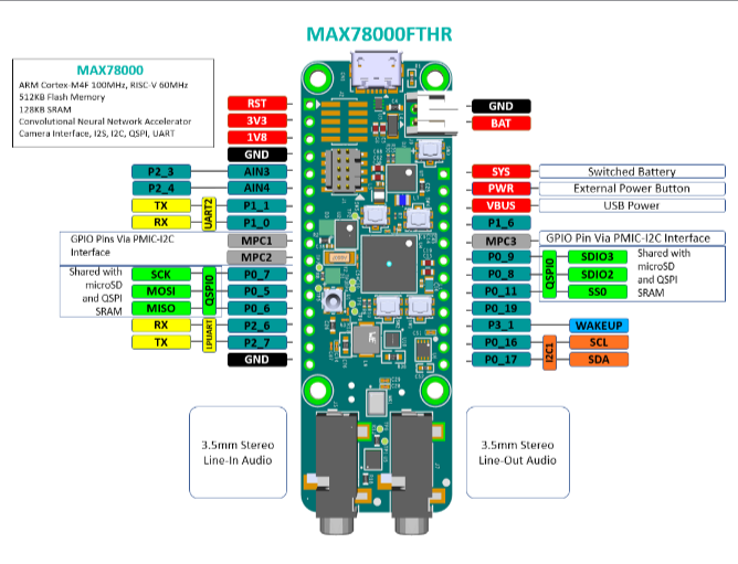
Figure 2. MAX78000FTHR Pinout Diagram (Taken from MAX78000FTHR Data Sheet).
An example setup, using three jumper cables and a breadboard is shown in Figure 3 and Figure 4 below. It is recommended that you use simple breadboard wires or jumper wires to physically ground the pins by plugging one end of the wires into ground and touching the other end of the wires to the pads.
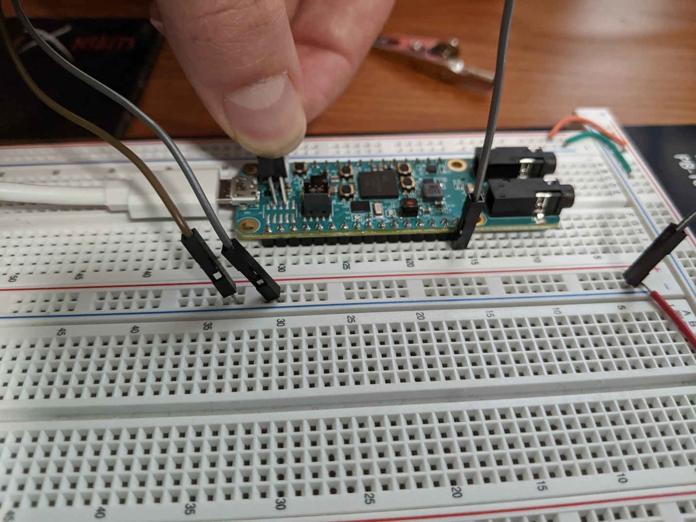
Figure 3. Example bootloader mode setup.
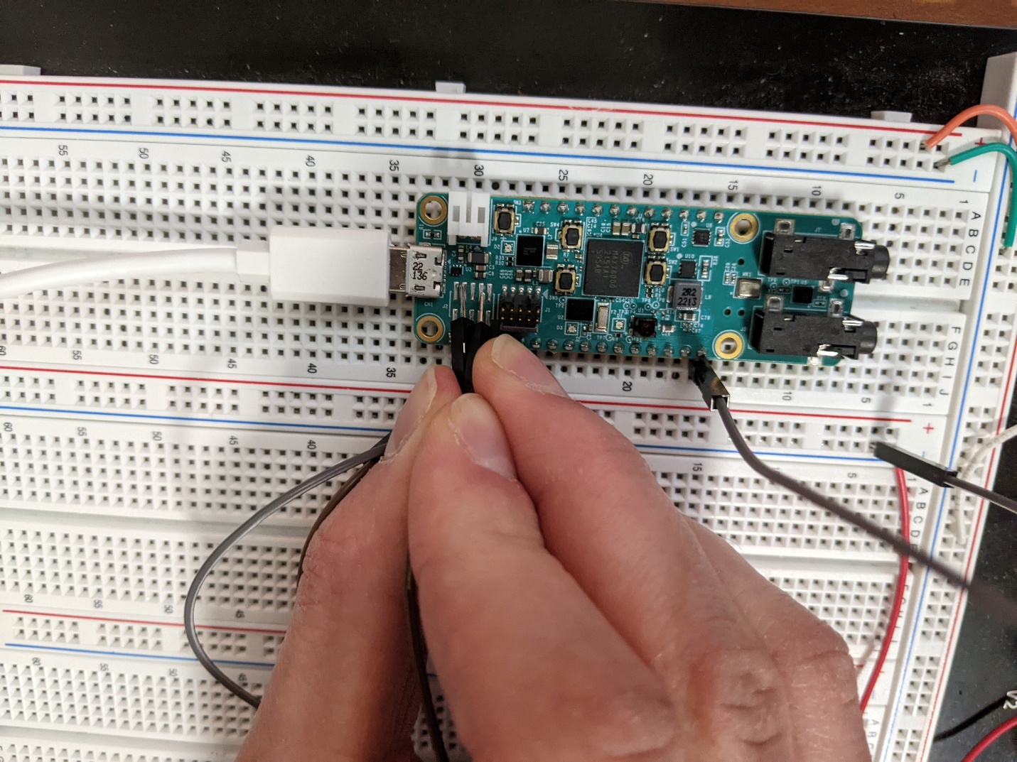
Figure 4. Example wiring setup (bird’s eye view).
STEP 2: After grounding the UART0 RX and SWDCLK pins, power the board back on or plug it into your computer and un-ground the pins (e.g. by removing the wires).
STEP 3: If you were successful in steps 1 and 2, your device should now be in bootloader mode. Check that you were successful by opening a serial connection using PuTTY or the serial monitor of your choice. Use Baud Rate 115200 b/s to connect as shown in Figure 5.
Note
When interacting with the boot ROM interface, you must send a CRLF (”\r\n”) ending rather than just a LF (”\n”). If using PuTTY, you may need to enable the “Implicit CR in every LF” option.
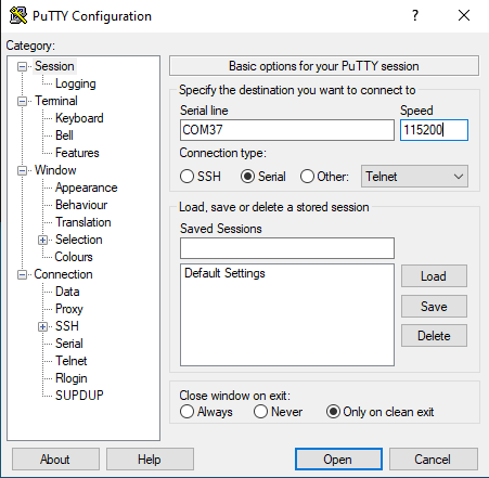
Figure 5. Serial monitor session configuration (NOTE: serial port numbers may vary).
Once you have opened the connection, you may need to press “ENTER” or “RETURN” once or twice for the bootloader status message (“CR>”) to appear (see Figure 6).
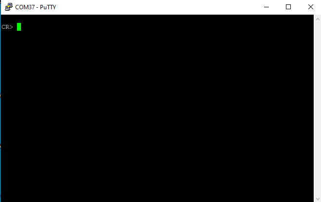
Figure 6. Serial output of device in bootloader mode.
STEP 4: With the device in bootloader mode, now close your serial connection. Next, use Python >= 3.10 to run the device unlock script “unlock.py.” Note: You will need to install the Python library, “pyserial” if you have not already. It is recommended that you use a virtual environment to do so.
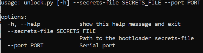
Figure 7. Help message for unlock.py.
The serial port you use will be the same port that you used in Step 3. The secrets file will be provided to you by the eCTF organizers.
If the unlock script runs successfully, you will be greeted by an output like in Figure 8.

Figure 8. Expected output for unlock.py.
STEP 5: Congratulations! You have now unlocked the MAX78000FTHR from the secure bootloader. Now, check your work by repeating steps 1-3. This time, you should see a different message (“ULDR>”) appear on the serial monitor (see Figure 9). If you see the message, then your reset was successful. The board’s program memory is now wiped completely clean and you can use the device for your own purposes.
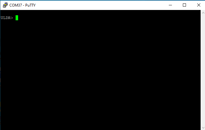
Figure 9. Expected serial output for an unlocked board in bootloader mode.
