System Overview
Warning
ARCHIVED PAST COMPETITION, FOR REFERENCE ONLY
Competition Components:
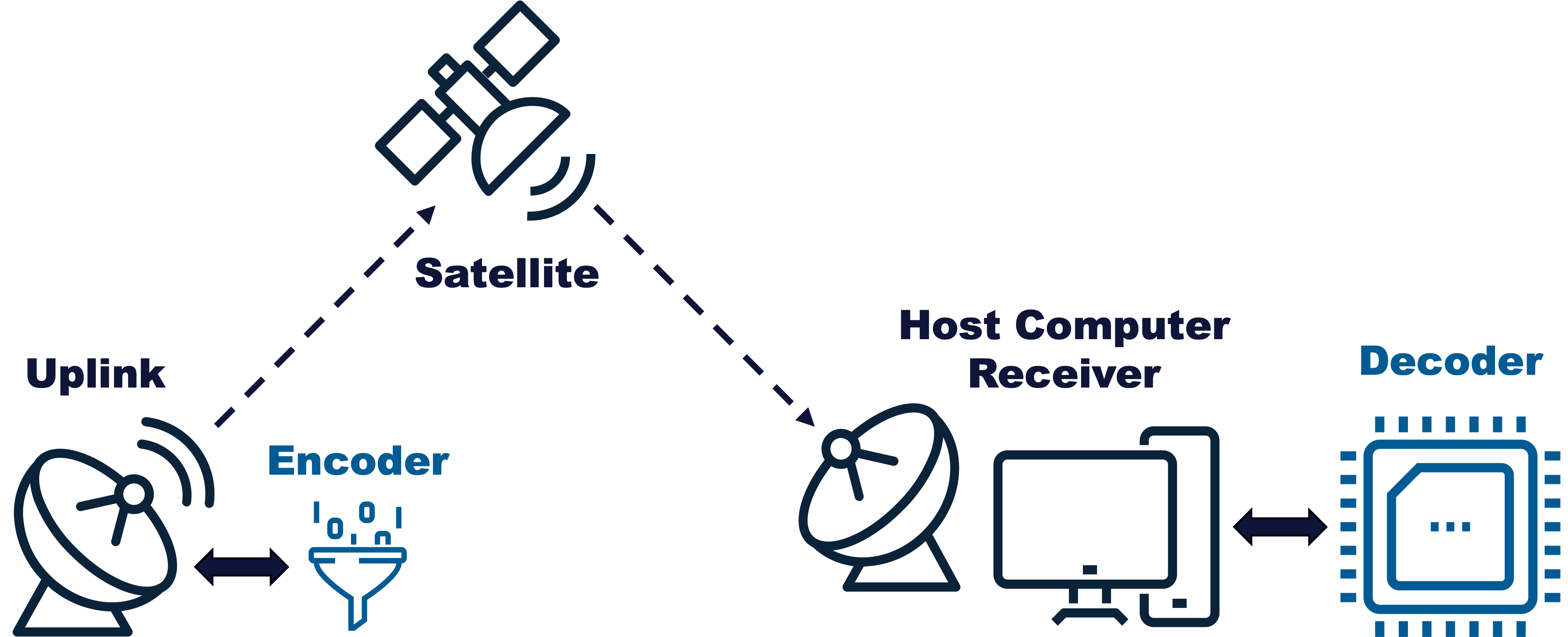
Your team’s design will consist of an Uplink and Encoder streaming data to a Satellite, a Host Computer, and a hardware Decoder. The Decoder firmware you design will securely decode TV frame data streamed over a satellite’s unidirectional data stream. The image below shows a high-level overview of the system architecture.

High-Level Satellite TV System
Uplink
The Uplink component of the Satellite TV system is responsible for sending frames to the Satellite to be broadcast to all Decoders. The Uplink will first send raw frames to the Encoder and will then forward the encoded frames to the satellite.
The Uplink is implemented as a Python script from the ectf25 module,
networked with the Encoder and Satellite. The Uplink will be provided to teams
and may not be modified.
Encoder
Teams are responsible for implementing an Encoder design utilized by the
Satellite System. Generated TV data frames are passed through the Encoder before
being broadcast to to a listening Decoder. The Encoder is
implemented as a Python script from the ectf25_design module, networked with the
Uplink (you may choose to use a different language, see
Allowed Programming Languages).
Satellite
The Satellite component of the Satellite TV System will run in a cloud environment managed by the eCTF Organizers. The Satellite takes encoded frames sent to it by the Uplink and forwards them to all listening TVs running on Host Computers.
The Satellite is implemented as a Python script from the ectf25 module,
networked with the Uplink. The Satellite will be provided to teams and may not
be modified.
Host Computer
The host computer is a general-purpose computer (i.e., your laptop or desktop) used to communicate with the Decoder over a serial interface through a number of Host Tools. These tools will be used to initiate the various functionalalities of the Decoder device (see Functional Requirements) and to read back status messages and data. To simplify the system, all Host Tools communicating with the device will be written by the organizers.
TV
The TV is the primary functionality running on the Host Computer. It connects to the Satellite to receive encoded packets, forwards them to the Decoder to be decoded, and prints the decoded frames to the screen.
The TV is implemented as a Python script from the ectf25 module.
The TV will be provided to teams and may not be modified.
Decoder
The main focus of your team’s work is on the Decoder device. A Decoder is implemented on an Analog Device MAX78000FTHR development board connected to a Host Computer over a USB-serial interface. The Decoder will be used to decode data being live streamed over a uni-directional communications link across multiple channels. The Decoder is responsible for maintaining active subscriptions and correctly decoding data frames on subscribed channels.
Development Resources
Teams will be provided the following resources:
- 3 un-keyed MAX78000FTHR board (the development boards)
These boards will be used for the development of your design. Instructions to run the host tools on a local computer to test the entire system using the physical hardware are found in Host Tools. These devices will not be able to run Attack Phase designs provisioned by the eCTF organizers. However, the development microcontrollers can be used to practice attacks against designs in the Attack Phase that are compiled locally by the team from source.
- 3 keyed MAX78000FTHR boards (the attack boards)
Boxes have small red stickers to indicate that they contain provisioned attack boards
These boards will be used for the Attack Phase to securely the load other teams’ designs that will be provided by the eCTF organizers. These devices are configured for use in the Attack Phase and therefore will be unusable during the Design Phase.